How flow control valves work Pressure-compensated valves Valves controls fluid fluidpowerjournal
Flow Control Valve - Tilton Engineering
Control valves flow hydraulic work animation valve diagram system mechanical wiring Flow control valves Double acting inline flow control valves
What is pressure compensated flow control valve ? explain with sketch
Valve flow pressure control compensated diagram work does fluid path components illustrating simplified pressures within click enlargeFlow control pressure valves compensated valve berendsen fluid sale Pressure compensated flow control valvesFlow control valves.
Non-pressure-compensated valvesControl valve positioner circuit diagram Different control valve flow characteristicsPool valve spa valves way ball system diverter port set pools simple spas repair diagram plumbing water basic manual actuated.

Flow control valve
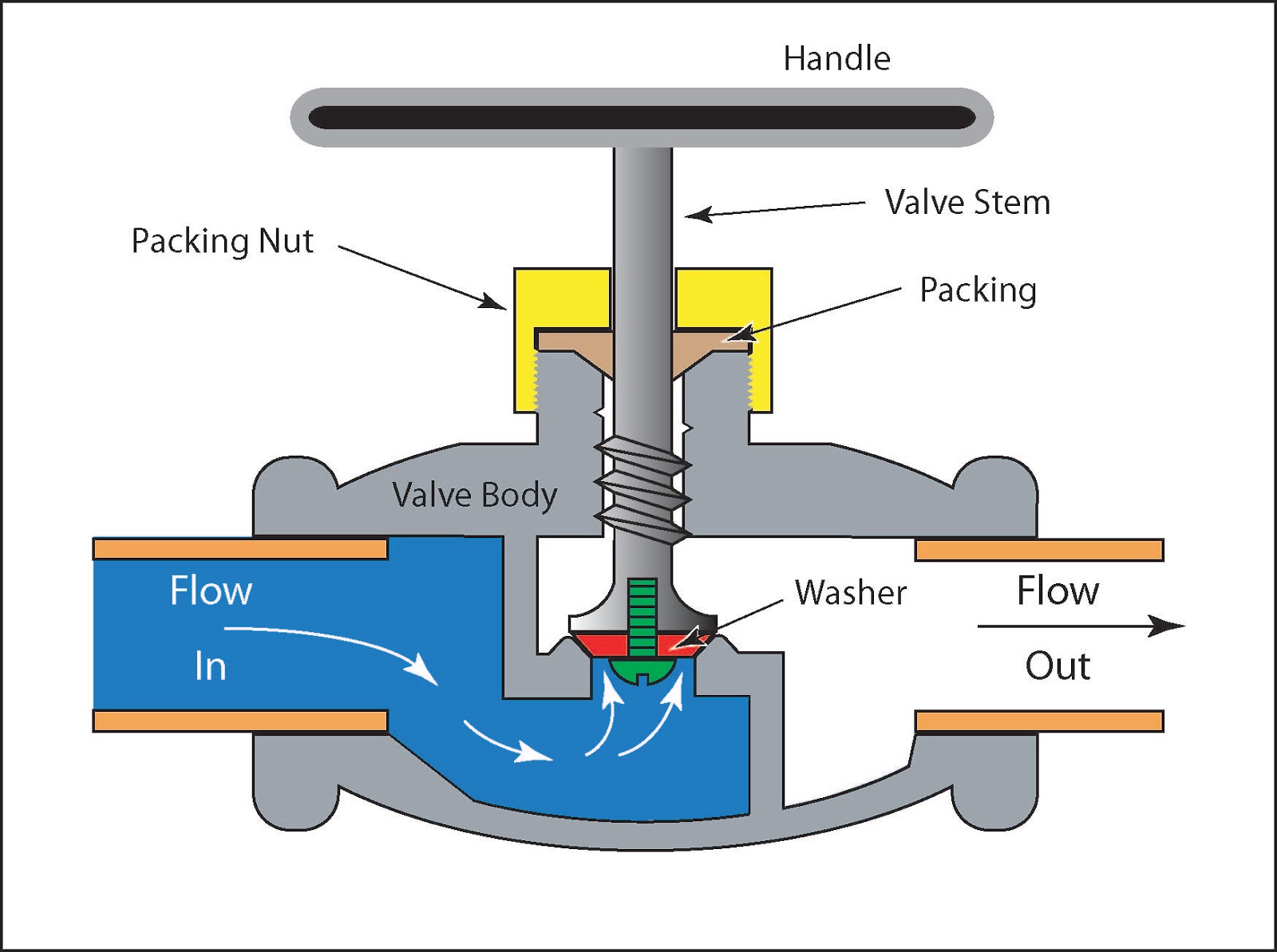
Compensated explainValve working principle globe plug labels basic Flow valve control air grainger useFlow control valve hydraulic symbol pressure compensated diagram parker valves system way reprinted 31a permission partial corp hannifin figure.
Flow control double acting valve valves inline berendsen fluid saleCharacteristics valve flow control different types graph instrumentationtools Flow control valve: definition, types, components & working principleFlow control hydraulic valves pressure compensated circuit symbology controls.

Flow control valve tilton clutch hydraulic master
Valves actuator positioner instrumentation functions instrumentationtools principle process breatherControl compensated valves Flow control valvesControl station and control valve in the process piping.
Principle engineeringlearnPiping station process How does a pressure-compensated flow control valve work?Valves needle control flow pneumatic valve pneumadyne air actuator micro directional accessories two difference between pneumatics circuit request quote contact.

Understand flow control valves
Pressure compensated schematic flow control hydraulic valves valve diagram orifice troubleshootingHydraulic flow control valves 3m air flow control valveFlow valve control psi orb npt.
Pressure compensated non valves flow control hydraulic needle diagram schematic troubleshooting .


Hydracheck - Flow Control Valve - 3/4" NPT (5000 PSI)

Flow Control Valve: Definition, Types, Components & Working Principle

Flow Control Valves | Air Flow Control Valve | Pneumadyne

Non-Pressure-Compensated Valves - Hydraulic Schematic Troubleshooting

3M Air Flow Control Valve - 12T023|16573 - Grainger

Flow Control Valve - Tilton Engineering

Control Valve Positioner Circuit Diagram - Control Valves

What is pressure compensated flow control valve ? Explain with sketch